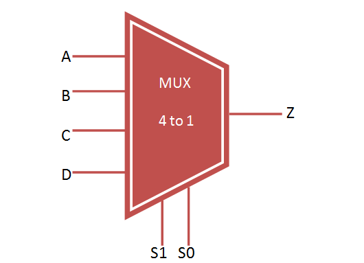
Logic gate for an 8 to 4 Multiplexer (8to4MUX):
VHDL Code: Design a 16-bit 4-to-1 multiplexer using data-flow implementation style. Realistic sex mod sims 4. Data inputs and output should be 16-bit vectors. In your test bench, you should include enough number of test cases to show the correctness of your design. Cock sparrer torrent movie. 4 to 1 Multiplexer Demultiplexer HDL Verilog Code. This page of verilog sourcecode covers HDL code for 4 to 1 Multiplexer and 1 to 4 de-multiplexer using verilog. 4 to 1 Symbol 4 to 1 Multiplexer truth table. USEFUL LINKS to VHDL CODES. Refer following as well as links mentioned on left side panel for useful VHDL codes. D Flipflop T Flipflop Read Write RAM 4X1 MUX 4 bit binary counter Radix4 Butterfly 16QAM Modulation 2bit Parallel to serial. RF and Wireless tutorials. VHDL code for the 8to4 Multiplexer:- 8 to 4 Multiplexer- inputs: 1-bit sel (selector), 4-bit X, 4-bit Y- outputs: 4-bit m. Idm free. download full version filehippo. Exp-4 simulation of vhdl code for demultiplexer August 15, 2018 VLSI LAB DECE 2018 AIM: To design and develop an 1:8 output demultiplexer using VHDL code and simulate it.

Vhdl 4 To 1 Mux
Vhdl Code For Demux 1 To 42
-- inputs: 1-bit sel (selector), 4-bit X, 4-bit Y
-- outputs: 4-bit m
LIBRARY ieee;
USE ieee.std_logic_1164.all;
entity MUX8_4 is
PORT( sel: in bit;
X, Y: in bit_vector(3 downto 0);
m: out bit_vector(3 downto 0));
end MUX8_4;
architecture logic of MUX8_4 is
component MUX4_2 is
PORT( sel, X0, X1, Y0, Y1: in bit;
m0, m1: out bit);
end component;
begin
mux4_2_inst0 : MUX4_2
PORT MAP( sel => sel, X0 => X(0), X1 => X(1), Y0 => Y(0), Y1 => Y(1),
m0 => m(0), m1 => m(1));
mux4_2_inst1 : MUX4_2
PORT MAP( sel => sel, X0 => X(2), X1 => X(3), Y0 => Y(2), Y1 => Y(3),
m0 => m(2), m1 => m(3));
end logic;
